

Information
More Information

HF + 50 MHz linear amplifier HF AMPLIFIERS/PREAMP


The IC-PW2 is Icom’s most advanced linear
amplifier and features a solid 1KW on the HF and 6m bands.
High Power and Full Duty Cycle Operation
The IC-PW2 uses new 65 V LDMOS power transistors (MRFX1K80HR5) and a high-efficiency power supply. Achieve a 1kW output with a 200V AC Input. The IC-PW2 instantly operates at full power once turned on. Use the PW2 for long contest hours or full-duty FT8 operation.
ncreased Linearity & Clean Transmission with the Digital Pre-Distortion (DPD) Technology (with the IC-7610)
the IC-7610. This technology corrects the signal distortion from the IC-PW2, by applying inverse distortion to the output signal from the IC-7610 exciter in advance.
2 × 6 Automatic Antenna Selector
Two radio inputs and six antenna connectors provide fully automatic antenna-switching capabilities. Each antenna can be independently selected when changing a band on either transceiver. You can operate it as if you had two linear amplifiers. When using dual independent receivers, which the IC-7610 and IC-7851 have, you can watch two bands at once by using two antennas.
Powerful SO2R Features
Single Operator Two Radios (SO2R) operation is possible with one IC-PW2. While you are making a call on one radio*1, you can watch another band on the other radio. The transmitter lockout function*2 prevents simultaneous transmission of two radios during SO2R operation.
SO2R Operation Possible with Just One Multi-band BPF
Conventional linear amplifiers require two multi-band bandpass filters (BPF) to prevent suppression of receive sensitivity by their own transmit signal when operating SO2R. However, the IC-PW2 automatically connects the multi-band BPF to the receiving radio when you select either radio to transmit. This makes SO2R operation possible with just one Multi-band BPF.
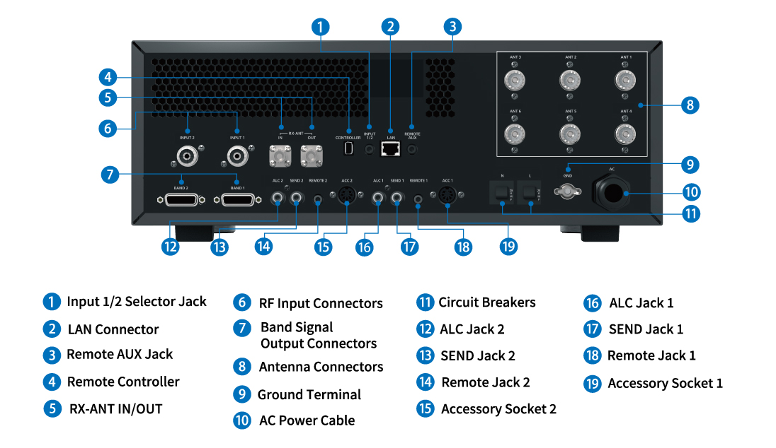
RX-ANT Connectors for Multi-band BPF and External Equipment
User supplied bandpass filters (BPF), preamps, and attenuators can be connected to the [RX-ANT] connectors. When you use two radios with the IC-PW2, one multi-band BPF can be shared with these radios by switching the receiving radio. In addition, the band switching of multi-band BPF can be controlled from the band signal output connector. The [BAND 1], [BAND 2] signal output connectors, can each be set to either [INPUT 1], [INPUT 2], transmitter side, or receiver side. It can be linked with band switching of various external devices.
User supplied bandpass filters (BPF), preamps, and attenuators can be connected to the [RX-ANT] connectors. When you use two radios with the IC-PW2, one multi-band BPF can be shared with these radios by switching the receiving radio. In addition, the band switching of multi-band BPF can be controlled from the band signal output connector. The [BAND 1], [BAND 2] signal output connectors, can each be set to either [INPUT 1], [INPUT 2], transmitter side, or receiver side. It can be linked with band switching of various external devices.
Use compatible Icom radios to get the full performance out of the IC-PW2. Accessing various settings is easy. When you operate the transceiver by changing bands and frequency tuning, the IC-PW2 automatically works in conjunction. It provides a rapid response in contests and multi-band operations.
Optional PC remote-control software will provide a remote-control operation through a LAN. Remote power ON/OFF from the PC and various operation of the radio will be possible.
The antenna tuner uses mechanical relays to retune the operating band in two to three seconds. The IC-PW2 has also succeeded in reducing unnecessary emissions during tuning. The antenna tuner works even when the power amplifier function is not used.
A remote-control cable (3 m, 9.8 ft) enables the amplifier to be mounted away from the radios for a big station installation. The 4.3 inch color display is a touch screen with a graphical user interface. Connected antennas are graphically shown on the display.
Other Features
High-efficiency and low noise cooling system
Various error detection circuits protect internal components
An SD card slot on the front panel for firmware updates and saving settings
Remote AUX jack for controlling an automatic tuning telescopic antenna
Antenna quick select function that can connect to priority antenna with simple action
Frequency coverage 1.9, 3.5, 7, 10, 14, 18, 21, 24, 28, 50 MHz bands (Amateur bands)
Output power 1 kW (180 ~ 264 V AC), 500 W (90 ~ 132 V AC)
Driving power Maximum 100 W
Power supply requirements 90 ~ 132 V AC or 180 ~ 264 V AC
Power consumption 2000 VA (100 V AC)
3000 VA (200 V AC)
Spurious emissions -60/-70 dB or less (HF/50 MHz band)
Antenna connector Input PL–239 × 2 (50 Ω)
Output PL–239 × 6 (50 Ω)
Tuner matching range 16.7 ~ 150.0 Ω (HF ~ 50 MHz)
Tuning accuracy VSWR 1: 1.5 or less
Tuning time Average 2 ~ 3 seconds
Maximum 15 seconds
Usable temperature range -10 ℃ ~ +40 ℃, +14 ℉ ~ +104 ℉
Dimensions (W×H×D) 425 × 149 × 445 mm, 16.7 × 5.9 × 17.9 in (Projections not included)
Weight (Approximate) 22 kg, 48.5 lb
Output power 1 kW
Driving power 100 W (Maximum)
Spurious emissions Less than –60 dB (HF bands)
Less than –70 dB (50 MHz)
Supplied Accessories
ACC cable (3 m, 9.8 ft)
Control cable (3 m, 9.8 ft)
Coaxial cable (3 m, 9.8 ft)
Mini plug cable (3 m, 9.8 ft)
Bracket for controller
Front plate (for separated RF unit)
Remote controller compatible
• 65V LDMOS power transistors
• High-efficiency internal power supply
• Built-in 2x6 automatic antenna selector
• Digital pre-distortion (DPD)
o 7610 only (OPC-2501 required)
• RX-ANT connectors for multi-band BPF
• Internal automatic antenna tuner
• SO2R, Single-Operator Two-Radio, capable
Accessories for ICOM ICPW2

OPC2501
Digital Pre Distortion for IC7610 and PW2
44.95

OPC599
13pin DIN to 7pin & 8pin DIN ADAPTER CABLE
64.95
Manufacturer Info

Copyright © 2025 R and L Electronics, Inc